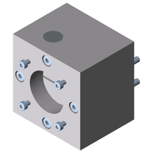
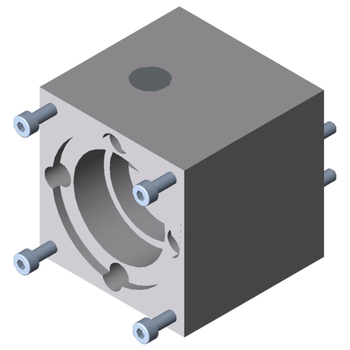
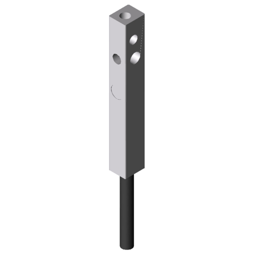
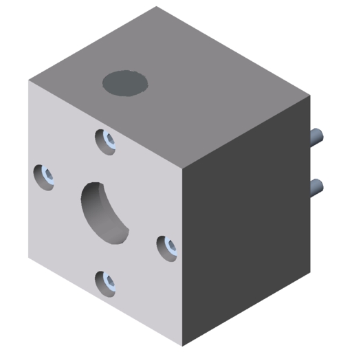
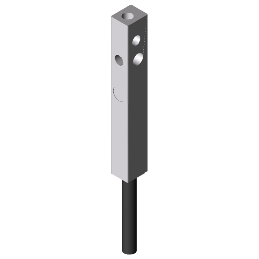
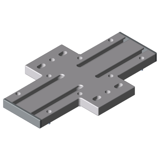
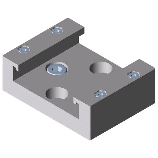
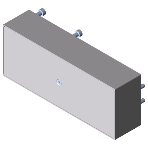
Linear Unit KGT 6 60 P20
0.0.706.00
Technical Data
Properties
| Article number | 0.0.706.00 |
|---|---|
| Line | line 6 |
| ESD-safe | No |
| Moment of Inertia, torsional | It = 1,23 cm4 |
| Moment of Inertia, x-axis | Ix = 28,09 cm4 |
| Moment of Inertia, y-axis | Iy = 43,46 cm4 |
| Total mass | m = m1 + H * m2 |
| Maximum operating load | Fx max = 1.000 N |
| Maximum force in direction y | Fy max = 2.000 N |
| Maximum force in direction z | Fz max = 2.000 N |
| Weight | m = 3,253 kg |
| Weight | m = 4,67 kg/m |
| Weight per length of the drive medium (timing belt, chain) | mlz = 0 kg/m |
| Efficiency | . = 0,9 |
| Max. speed | up to 1 m/s |
| Delivery unit | 1 pce. |
| Basic mass (when stroke length = 0 mm) | m1 = 3,253 kg |
| Mass per mm of stroke | m2 = 4,24 g/mm |
| Max. acceleration | amax = 15 m/s2 |
| Max. speed | Vmax = 1 m/s |
| Repeat accuracy | . = 0.01 mm |
| Mass moment of inertia when stroke length = 0 mm | J0 = 30,21 kg mm2 |
| Mass moment of inertia per kg of payload | JN = 10,1 kg mm2/kg |
| Mass moment of inertia per m of stroke | JH = 43,1 kg mm2/m |
| Stroke max. | Hmax = 2.600 mm |
| max. drive torque | . = 3,7 Nm |
| Maximum moment around the x axis | Mx max = 15 Nm |
| Maximum moment around the y axis | My max = 120 Nm |
| Maximum moment around the z axis | Mz max = 120 Nm |
| Frictional moment | . = 0,2 Nm |
| Safety clearance | smin = 26 mm |
| Support width when Fy max. | . = 850 mm |
| Support width when Fz max. | . = 650 mm |
| Stroke | h = 20 mm/r |
| Resistance Moment, x-axis | Wx = 8,19 cm3 |
| Resistance Moment, y-axis | Wy = 14,44 cm3 |
Description
S1: distance to the fixed bearing (13mm) + safety distance (Smin = 26mm) + n x spindle support (16mm)
S2: distance to floating bearing (11mm) + safety distance (Smin = 26mm) + n x spindle support (16mm)The safety distance of 26mm is in all variants the free area, in which e.g. during the reference motion procedure is driven.
In applications with a long travel distance, travelling spindle supports keep everything running smoothly and precisely without sacrificing dynamics. Radial stabilisers on the inside of the axis provide perfect support for the specially shaped spindle regardless of the stroke length and carriage position.
Thanks to its installation dimensions of just 60x60 mm and two Line 6 groves on its side flanks, Linear Unit KGT 6 60 is very easy to integrate into constructions. Featuring a spindle lead of 20 mm per revolution, the system can reach a speed of up to 1 m/s, even at maximum stroke. Acceleration is up to 15 m/s2.
The carriage runs on two recirculating ball units that exhibit minimal reversal play during a change of direction. This enables reliable positioning with a repeatability of 0.01 mm at a high feed force of up to 1000 N. The powerful ball screw unit is thus ideal as a single axis for moving tools and workpieces with absolute precision. When combined with additional KGT 6 60 units and other item Linear Units, the spindle axis can be used to build precise and strong 2D and 3D gantries.
An unbroken cover strip conceals the inner workings and therefore provides protection from soiling. The spindle is low-maintenance and features lifetime lubrication.
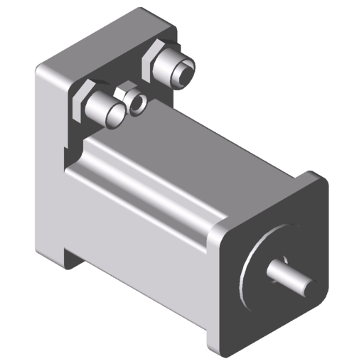
These plug-and-play solutions can be connected to item Motors in 40 mm and 60 mm sizes without the need for additional machining. Drive Set KGT 6 60 universal is available for use with other drives.
The whole selection and design process can be completed in next to no time when using item MotionDesigner®. The software maps out the entire system to suit your transport task. The Linear Unit is supplied as a ready-to-install solution in a custom length.
Zum Anschluß anderer Motoren mit der Baugröße 60 x 60 mm steht der Antriebssatz KGT 6 60 universal zur Verfügung.
-------------- without support
D = Speed [1/min]
L = Length of shaft [mm]
Maximum spindle speed with and without KGT 6 60 P 20 spindle supports
The spindle supports keep the maximum unsupported spindle length more or less constant. This means the critical speed of 3000 min-1 is constant over the entire possible stroke range.
Load Calculation
Downloads
CAD Data
Accessories
Classification
Classifications are industry-wide product data standards that are used, among other things, to support structured processing in ERP and e-business systems. Do you need the classification data for all item products for your e-procurement system? If so, please don’t hesitate to contact us.
eCl@ss 8.0
23301702
eCl@ss 7.1
23301702
eCl@ss 11.0
23301702
eCl@ss 5.0
23329090
eCl@ss 5.1
23329090
eCl@ss 6.0.1
23301702
UNSPSC 7.0
26111506
UNSPSC 9.0
26111506
eCl@ss 4.0
36400806
eCl@ss 4.1
36400701
Customs tariff number
84879090

