Technical Data
Properties
| Article number | 0.0.605.02 |
|---|---|
| Line | line 8 |
| ESD | ESD-safe = No |
| Moment of Inertia, torsional | It = 21,28 cm4 |
| Moment of Inertia, x-axis | Ix = 135,41 cm4 |
| Moment of Inertia, y-axis | Iy = 175,54 cm4 |
| Total mass | m = m1 + H * m2 |
| Maximum operating load | Fx max = 1.500 N |
| Maximum force in direction y | Fy max = 1.500 N |
| Maximum force in direction z | Fz max = 1.000 N |
| Weight | m = 9,844 kg |
| Weight spec. length [g/mm] | m = 8,771 g/mm |
| Weight, spec. Length | m = 8,771 kg/m |
| Weight per length of the drive medium (timing belt, chain) | mlz = 0,2 kg/m |
| Efficiency | . = 1 |
| Delivery unit | 1 pce. |
| Basic mass (when stroke length = 0 mm) | m1 = 9,844 kg |
| Mass per mm of stroke | m2 = 8,771 g/mm |
| Max. acceleration | amax = 10 m/s2 |
| Max. speed | Vmax = 10 m/s |
| Repeat accuracy | . = 0.1 mm |
| Mass moment of inertia when stroke length = 0 mm | J0 = 3.316 kg mm2 |
| Mass moment of inertia per kg of payload | JN = 1.117,1 kg mm2/kg |
| Mass moment of inertia per m of stroke | JH = 447 kg mm2/m |
| Stroke max. | Hmax = 5.600 mm |
| max. drive torque | . = 50 Nm |
| Maximum moment around the x axis | Mx max = 50 Nm |
| Maximum moment around the y axis | My max = 100 Nm |
| Maximum moment around the z axis | Mz max = 150 Nm |
| Frictional moment | . = 2,5 Nm |
| cleanroom suitability | Yes |
| Safety clearance | smin = 63,5 mm |
| Support width when Fy max. | . = 1.900 mm |
| Support width when Fz max. | . = 2.000 mm |
| Stroke | h = 210 mm/r |
| Resistance Moment, x-axis | Wx = 29,77 cm3 |
| Resistance Moment, y-axis | Wy = 43,89 cm3 |
Description
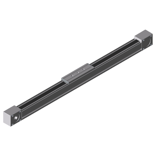
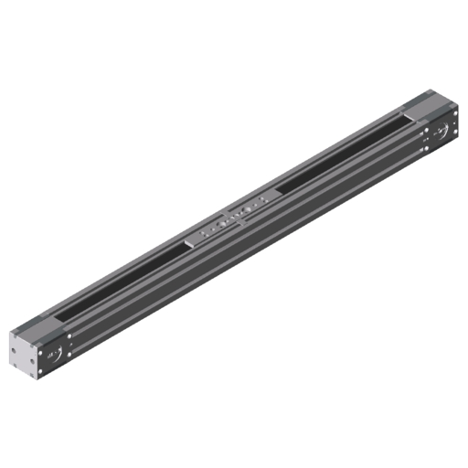
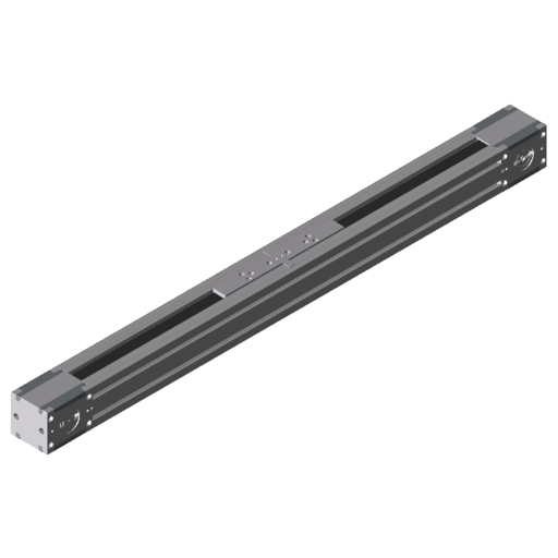
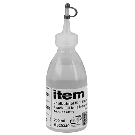
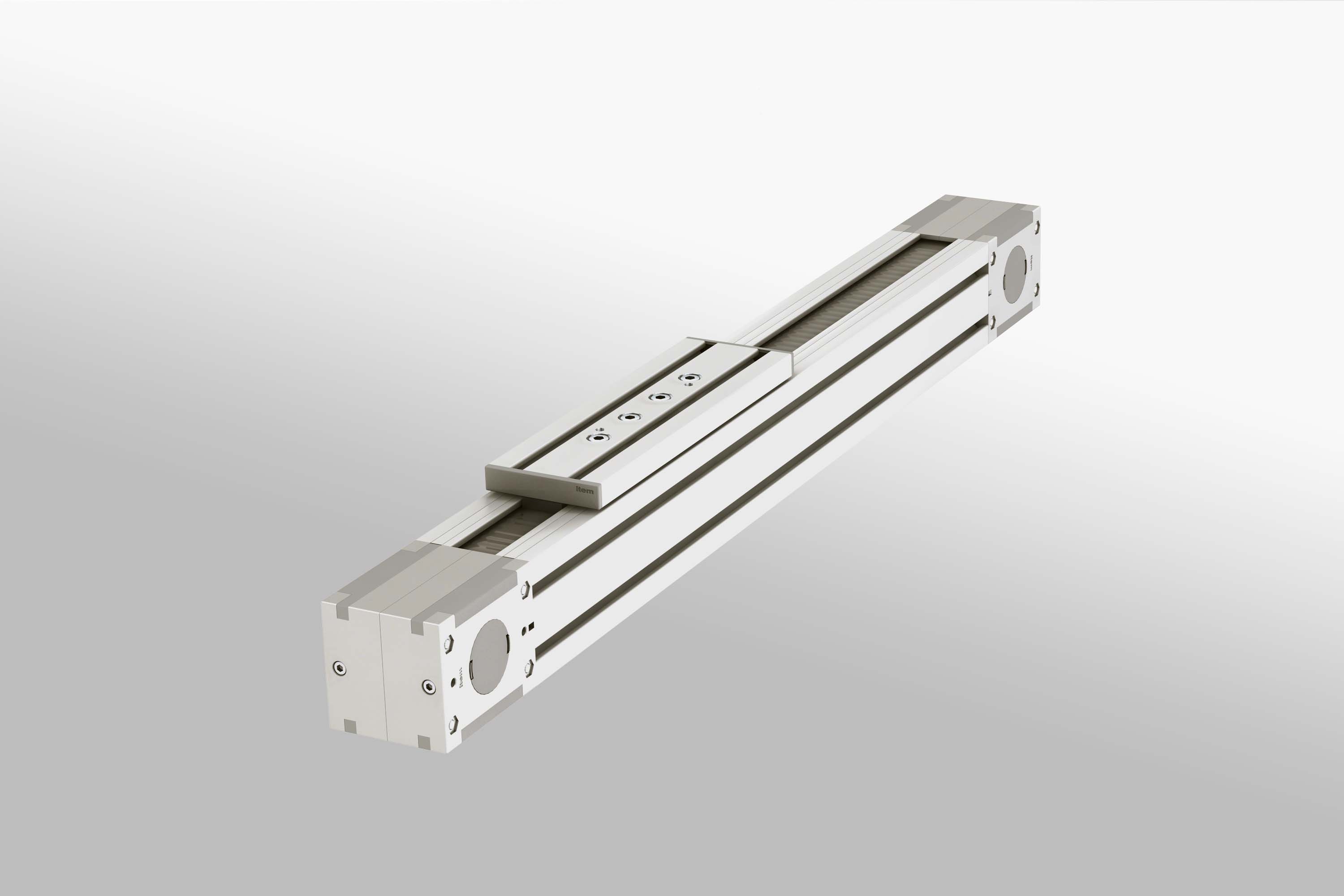
Guide slide with four-piece roller-bearing mounting, oil-lubricated roller contact (re-lubrication every 6 months or every 2500 km)
Linear Units KLE boast exceptional precision and low-vibration linear movement.
It should not exceed 1mm/m.
The KLE profile must be given appropriate support if the linearity of movement has to be very precise.
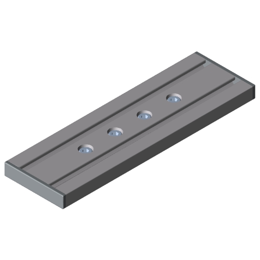
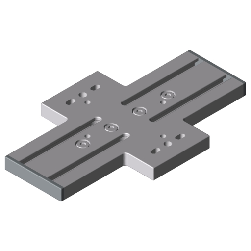
Two pinning holes are provided in the KLE 8 80x80 cover plate for this purpose.
It is advisable to use the dowel pins supplied with the carriage set in combination with the carriage plate.
KLE 8 80x80: Dowel Pin ISO 2338 6h8x40
If not using the original carriage plates, the pattern of holes must be copied from the drawings and transferred onto the custom carriage constructions.
v = vertical orientation
Maximum possible acceleration in relation to moved mass and installation orientation
Assembly Instructions
Variants
Sort by
| Line: 5 | Stroke length: 1 ... 2800 | Guide type: Shaft D6 | Timing Belt width: 16 mm | |
| Line: 6 | Stroke length: 1 ... 5750 | Guide type: Shaft D10 | Timing Belt width: 25 mm | |
| Line: 8 | Stroke length: 1 ... 5600 | Guide type: Shaft D14 | Timing Belt width: 34 mm |
Load Calculation
Downloads
Accessoires
Classification
Classifications are industry-wide product data standards that are used, among other things, to support structured processing in ERP and e-business systems. Do you need the classification data for all item products for your e-procurement system? If so, please don’t hesitate to contact us.
eCl@ss 8.0
23301702
eCl@ss 4.1
36400701
eCl@ss 5.0
23329090
eCl@ss 5.1
23329090
UNSPSC 7.0
26111506
UNSPSC 9.0
26111506
eCl@ss 6.0.1
23301702
eCl@ss 7.1
23301702
eCl@ss 11.0
23301702
eCl@ss 4.0
36400806
Customs tariff number
84879090


